
Insights
How much do structural steel dimensional tolerances vary? | Frame design based on JIS G 3192 tolerances and lot variations
"It doesn't fit when assembled, even though it was cut according to the drawing." This is a common issue with frames made from structural steel. The cause is often not a machining error, but rather that the dimensions of the material itself are varying. How much tolerance does JIS G 3192 allow for angle and channel steel? And how should frames be assembled given these tolerances? We will organize the key considerations for ordering electrical panel enclosures and frames.
Conclusion: Structural Steel Does Not Arrive "Exactly as Nominal Dimensions"
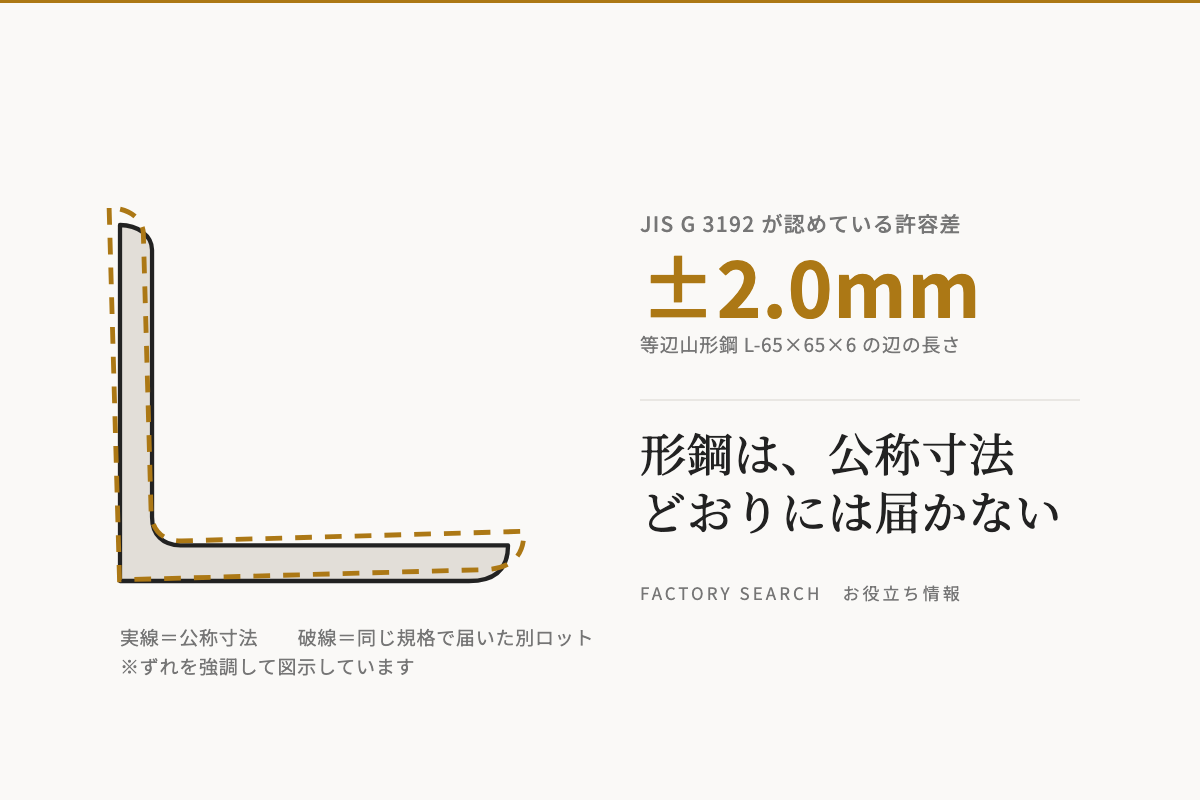
Even if L-65×65×6 is specified in the drawing, the actual leg length of the material received will almost never be exactly 65.0mm. JIS G 3192 (Dimensions, Mass and Permissible Variations of Hot Rolled Steel Sections) allows a tolerance of ±2.0mm for angle steel with leg lengths between 50mm and less than 100mm. Thickness, length, and squareness also vary within their respective tolerance ranges.
In other words, the premise that "if you buy standard products, you will receive material of the same dimensions" does not hold true. If you design and cut without accounting for this, frames that fit individually will no longer fit when arranged together.
What you will learn from this article
- Specific tolerance values allowed by JIS G 3192 for angle and channel steel
- How much lot variation impacts practical applications
- The mechanism by which individual frames fit, but overall length deviates in connected panels
- Four processes that manufacturers use to absorb variations
- What buyers should communicate in drawings and instructions
Tolerances Allowed by JIS G 3192

Leg Length (A・B) Can Vary by up to ±4.0mm
The tolerance for the leg length of angle steel is determined incrementally by the leg size.
| Leg Length A・B | Tolerance | Main Applicable Sizes |
|---|---|---|
| Less than 50mm | ±1.5mm | L-25×25, L-40×40, etc. |
| 50mm to less than 100mm | ±2.0mm | L-50×50, L-65×65, L-75×75, etc. |
| 100mm to less than 200mm | ±3.0mm | L-100×100, L-150×150, etc. |
| 200mm or more | ±4.0mm | L-200×200, L-250×250, etc. |
L-65×65×6, commonly used for electrical panel enclosures, falls into the "50mm to less than 100mm" category, meaning that a leg length within the range of 63.0mm to 67.0mm is within specification. Considering a 4mm range, this is likely much larger than what one might intuitively expect.
Thickness Tolerance Also Varies with Leg Size
| Thickness t | Leg A Less Than 130mm | Leg A 130mm or More |
|---|---|---|
| Less than 6.3mm | ±0.6mm | ±0.7mm |
| 6.3mm to less than 10mm | ±0.7mm | ±0.8mm |
| 10mm to less than 16mm | ±0.8mm | ±1.0mm |
| 16mm to less than 25mm | ±1.0mm | ±1.2mm |
| 25mm or more | ±1.0mm | ±1.5mm |
"Squareness" is Often Overlooked
When discussing dimensions, attention tends to focus on leg length and thickness, but it is squareness that affects frame accuracy. JIS G 3192 specifies the squareness of angle steel as "2.5% or less of leg B."
- For L-65×65, 65 × 2.5% = approx. 1.6mm
- For L-100×100, 100 × 2.5% = 2.5mm
Material with an "open/closed angle" by this amount will be delivered as within specification. Even if the leg lengths are exact, if the angle is off, the diagonals of the assembled frame will not match. This tolerance is why, when discussing frame accuracy, it is said that one must "look not only at the outer dimensions and hole pitch, but also at the angles and diagonals."
Standard Length Material Can Be up to +60mm at 11m
The length tolerance is "+40/-0mm for 7m or less," and for lengths exceeding 7m, an additional 5mm is added to the plus side for every 1m increment. For an 11m standard length material, this means +60/-0mm. Since the length can only deviate to the plus side, it is assumed that the cutting side will measure the material before determining the dimensions.
Source: JIS G 3192 "Dimensions, Mass and Permissible Variations of Hot Rolled Steel Sections." Values are based on the tolerances for angle steel in the same standard. For actual orders, please refer to the latest version of the standard.
In Practice, Leg Length and Angle Vary by "Approx. ±1.5mm"
While variations rarely reach the upper limits of the standard, in steel fabrication, it is understood that leg length and angle can change by approximately ±1.5mm when the lot changes. This means that even if you order the same standard and size, material with different dimensions may arrive if the delivery time is different.
The tricky part is that this difference appears "consistently per lot." Instead of random variations in each piece, materials from the same lot will collectively shift in the same direction. Therefore, simply measuring one piece and finding it acceptable does not guarantee that the entire lot is fine.
As an example of manufacturing that accounts for this variation, the approach to accuracy and tolerance in angle frame manufacturing published by a 78-year-old steel fabrication manufacturer is a useful reference. It specifically explains process design that determines cutting dimensions and assembly order based on the premise that structural steel is "not identical material."
Fits Individually, But Overall Length Deviates in Connected Panels
A common issue with electrical panels and cubicles is "panel arrays," where panels are arranged side-by-side. Even if individual panels are accurate, the overall length can become misaligned the moment they are connected.
For example, consider connecting 10 frames with an individual tolerance of +0 to -1.5mm, each W800. The designed overall length is 8,000mm.
If tolerances accumulate as is
-1.5mm × 10 panels = maximum -15mm to -20mm
While "1.5mm is generally acceptable" for a single unit, connecting 10 panels results in a difference that makes on-site installation impossible.
This is where the aforementioned squareness comes into play. Frames assembled with material where the angle is off will have diagonal deviations even if the outer dimensions match. Even if the diagonal deviation is slight for each panel, it accumulates as a continuous dimension in a panel array.
This means that individual accuracy and panel array accuracy must be built in as separate considerations. In an actual manufacturing example where a 10-panel array of 8,000mm is kept within ±2mm overall length, the tolerances are absorbed by dividing the process into four steps: cutting accuracy, hole positioning, assembly order, and final distortion removal, assuming that tolerances will accumulate.
Where to Absorb Variations
The variation in material dimensions cannot be changed. What can be changed is "in which process to absorb it." Sites that finish structural steel frames with high accuracy generally focus on the following four points:
1. Cutting Accuracy
Cut from standard length material in-house, determining cutting dimensions based on actual measurements for each lot. If material is cut according to drawing dimensions without checking actual measurements, the first deviation will occur here.
2. Hole Drilling
Determine hole positions assuming connection in a panel array. If holes are drilled based only on individual drawings, the connecting holes will not align when assembled.
3. Assembly Order
Consider the order of assembly to avoid cumulative errors. Determine the sequence, including the relationship between the main body and the base (channel base).
4. Final Distortion Removal
Distortion is inevitable with welding, so it must be completely removed in the final process. This is where angles, diagonals, and overall length are finalized. Conversely, in sites without a distortion removal process, the product will inherit the material variations as they are.
What Buyers Should Communicate in Drawings and Instructions
Some aspects cannot be fully addressed by the manufacturer's efforts alone. Communicating the following three points at the quotation and ordering stage will reduce rework:
- Presence and number of connected panels: If only individual drawings are provided, the manufacturer cannot anticipate cumulative errors during connection. If "W800 × 10 panels" is communicated, the design of cutting dimensions and assembly order will change.
- Which dimensions to prioritize: Should overall length be prioritized, or hole pitch? Since not everything can be prioritized simultaneously, indicate the datum surface and priority order.
- Post-surface treatment processes: When hot-dip galvanizing is performed, holes and threads may be filled due to the plating thickness. Confirm before ordering whether post-plating drilling and re-tapping can be requested.
Summary
- JIS G 3192 allows tolerances of ±1.5 to ±4.0mm for the leg length of angle steel and "2.5% or less of leg B" for squareness.
- In practice, leg length and angle vary by approximately ±1.5mm when the lot changes, and this deviation is consistent per lot.
- Even with an individual tolerance of -1.5mm, connecting 10 panels can result in a cumulative deviation of up to -15 to -20mm.
- Variations can be absorbed in four processes: cutting accuracy, hole drilling, assembly order, and final distortion removal.
- Buyers should communicate the "number of connected panels," "dimensions to prioritize," and "necessity of post-plating treatment."
Frequently Asked Questions
- Q. Does a mill sheet guarantee dimensions?
- A. A mill sheet is a certificate of chemical composition and mechanical properties; it does not guarantee the actual dimensions of individual materials. Dimensions will vary within the JIS tolerance range. If dimensional accuracy is required, assume that the manufacturer will measure the material before proceeding with cutting and assembly.
- Q. Will specifying tighter tolerances solve the problem?
- A. The tolerances of the material itself cannot be changed, so simply specifying tighter tolerances will not solve the problem. The solution lies in determining cutting dimensions that account for variations and in performing final distortion removal. It is more effective to specify which dimensions to prioritize (overall length / diagonal / hole pitch).
- Q. Is it the same for channel steel?
- A. Yes, tolerances are defined by the same JIS G 3192, and the approach is similar. Channel bases often serve as the datum surface for frames, so the effects of squareness and bending can propagate throughout the entire frame.
- Q. Can you handle a single special frame?
- A. It depends on the company. Steel fabrication manufacturers who regularly handle structural steel frames may be able to accommodate prototyping from a single unit.
Related articles
Industrial Angle Frame Manufacturing
Manufacturing of angle frames and stands for distribution boards and cubicle enclosures. E…